Many 3D vision techniques are used for robot guidance and industrial inspection applications.
More often than not, it is necessary to empower robots with the ability to become autonomous, identify, pick and place parts and collaboratively work with human operators. To accomplish this requires that such systems employ a number of machine vision techniques including photogrammetry, stereo vision, structured light, Time of Flight (TOF) and laser triangulation techniques to perform the task of localizing and measuring objects.
|
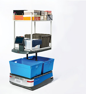
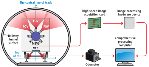
Figure 1: 6 River Systems’ collaborative automation warehouse robot, known as Chuck, uses TiM LiDAR sensors from SICK to build a map of the environment and lead warehouse associates to the correct location to pick products. SCENES AND OBJECTSDepending on the application, the vision system may be either scene-related or object related. In scene-related applications, the camera is generally mounted on a mobile robot and algorithms such as simultaneous localization and mapping (SLAM) are used to construct or update a map of the surrounding environment. In object-related tasks, a camera, cameras, laser or TOF system is attached to the end-effector of an industrial robot allowing new images to be captured as the end-effector is moved. Of course, with different tasks, different kinds of 3D imaging systems may be required. In scene-related applications, the robot needs to be aware of the surroundings and whether any objects or people are present to hinder its path. In applications such as these, it may also be necessary to add a capacity to pick and place objects. Examples of such applications include self-driving cars, warehouse pick-and-fetch robots and military-based robotic systems designed to identify, for example, suspicious objects. Unlike object-related tasks that are designed to perform specific pick-and-place functions, these systems must also incorporate methods to localize and map their local space and, once located, must perform a specific function such as fruit picking. In one sense, these systems add an extra sophistication to robotics systems and to do so, a number of different hardware and software options can be used. Figure 2: At the Southwest Jiaotong University, Dong Zhan and his colleagues have designed and built a dynamic railway tunnel 3D clearance inspection based on a multi-camera and structured-light vision system. MAPPING THE ENVIRONMENTTo build a map of the surrounding environment, the problem of scene mapping is solved by incorporating LiDAR scanning range finders from companies such as SICK (Minneapolis, MN, USA; www.sick.com) and Velodyne (San Jose, CA, USA; https://velodynelidar.com), onto robots or autonomous vehicles. At 6 River Systems (Waltham, MA, USA; https://6river.com), for example, the company’s collaborative automation warehouse robot known as Chuck uses TiM LiDAR sensors from SICK to build a map of the environment and lead warehouse associates to the correct location to pick products (Figure 1). In a similar application, RK Logistics Group (Fremont, CA, USA; www.rklogisticsgroup.com), partnered with Fetch Robotics (San Jose, CA, USA; www.fetchrobotics.com) to increase employee productivity by automating the task of transporting products from one part of the RK Logistics’ warehouse to another (see “Autonomous mobile robots target logistics applications,” Vision Systems Design, May 2018; http://bit.ly/VSD-AMR). Fetch Robotics’ Freight autonomous mobile robot employs a SICK TIM571 LiDAR scanning range finder interfaced to its on-board computer over an Ethernet switch. Using TOF measurement, the TIM571 emits an 850nm laser pulse which is scanned over a 220° field of view (FOV) using a moving mirror. To evaluate the most optimal system for autonomous vehicles, Simona Nobili and her colleagues at the Ecole Centrale Nantes (Nantes, France; www.ec-nantes.fr) have analyzed two common LiDAR configurations: the first based on three planar SICK LMS151 LiDAR sensors and the other on a Velodyne 3D LiDAR VLP-16 sensor. Implementing a SLAM algorithm, the systems they developed used three SICK LMS151 sensors placed at 50 cm from the ground level on a Renault Zoe ZE electric car and a Renault Fluence equipped with a 16-channel Velodyne LiDAR PUCK (VLP-16) placed above the roof. In their research, the researchers found that maps built with VLP-16 data were more robust against common medium-term environment changes such as cars parked on the roadside and that single sensor implementations such as these were easier to install and calibrate (see “16 channels Velodyne versus planar LiDARs based perception system for Large Scale 2D-SLAM,” http://bit.ly/VSD-VEL). 3D MEASUREMENTSOf course, many machine vision applications only require object-related tasks such as 3D measurements to be performed. Here, depending on the nature of the product to be inspected, several different methods exist, one of the most commonly used being structured laser light analysis or laser line profiling. In this method, a structured laser light is either moved across an object or allowed to impinge on the object as it moves along conveyor. Single lines of the reflected laser light are then digitized by an industrial camera and the distance of each surface point is computed to obtain a 3D profile of the object. In order to build a system like this, developers have the option of using single laser line sources from companies such as Coherent (Santa Clara, CA, USA; www.coherent.com) and Z-Laser (Freiburg, Germany; www.z-laser.com) and separate cameras with which to digitize the reflected light. Such systems are used in numerous machine vision applications including electronics inspection, dimensional parts analysis and automotive tire tread inspection. One of the more novel applications of this technology has been to accurately produce 3D measurements of railway tunnels. In a system developed at the Southwest Jiaotong University (Chengdu, China; https://english.swjtu.edu.cn/), Dong Zhan and his colleagues built a dynamic railway tunnel 3D clearance inspection based on a multi-camera and structured-light vision system (Figure 2). To capture 3D images of the tunnel, seven MVC1000SAM GE60 1280 × 1024 industrial cameras from Microview (Beijing, China; http://www.microview.com.cn) with 5-mm focal length lenses from Kowa (Aichi, Japan; www.kowa.co.jp) are used to capture seven reflected laser lines from Z-Laser Model ZM18 structured lasers, while another two cameras and lasers are used to monitor the rail. Installed on the front of a train, captured images are then triggered by the optical encoder to capture a 2D laser map of the tunnel. Image processing software is then used to reconstruct the surface of the tunnel (http://bit.ly/VSD-MSVS). In such systems, it is vitally important to calibrate the camera systems used. Realizing this, developers of such laser/camera systems have developed products that embed both cameras and lasers and are supplied pre-calibrated. Here, such products as the DSMax 3D laser displacement sensor from Cognex (Natick, MA, USA: www.cognex.com), the LJ-V Series laser profilometer from Keyence (Osaka, Japan; www.keyence.com) and the Gocator 3D laser line profile sensors from LMI Technologies (Burnaby, BC, Canada; www.lmi3d.com) all offer systems integrators an easy way to configure laser-based 3D profiling systems. STEREO CAMERASWhile both scanning range finders and laser-based implementations represent active methods of 3D imaging, passive methods that use one or two cameras can be equally as effective. Often two calibrated cameras are used to identify single points in 3D space and this information is used to generate a depth map. However, this need not be the case. By mounting a single camera onto a robot arm’s end effector, for example, and moving the camera in 3D space, two separate images can be captured, and a depth map generated from them. Two companies that have developed this capability are Motoman (Miamisburg, OH, USA; www.motoman.com) and Robotic Vision Technology (RVT; Bloomfield Hills, MI, USA; http://roboticvisiontech.com). For its part, Motoman’s MotoSight 3D CortexVision simplifies the use of 3D vision in robotic guidance applications using a single camera mounted to the robot. In operation, the system takes multiple images and automatically refines the position of the camera to optimally locate the part. (see “Robot Guidance,” Vision Systems Design, November 2008; http://bit.ly/1pUVMUG). RVT uses a similar concept to locate parts in 3D space. In RVT’s eVisionFactory software, an AutoTrain feature automatically moves a robot and camera through multiple image positions as it measures features of the part being imaged. While single-camera systems can be used to locate parts in 3D space, the positional accuracy of the robot will determine how accurately specific objects can be located in 3D space.
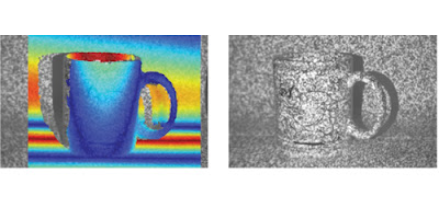
Just as active laser and camera systems need to be accurately calibrated, so too do dual-camera configurations. Like active/laser camera systems that are offered as products that embed both cameras and lasers and are supplied pre-calibrated, so too are passive stereo systems. These often employ two (or more) stereo vision cameras and are pre-calibrated, saving systems developers the task. The most well-known of these 3D stereo camera systems are the Bumblebee series from FLIR Integrated Imaging Solutions (Richmond, BC, Canada; www.flir.com/mv), the SV-M-S1 from Ricoh (Tokyo, Japan; https://industry.ricoh.com) and the ZED from Stereolabs (San Francisco, CA, USA; www.stereolabs.com). While the SV-M-S1 and ZED use a fixed two-camera implementation, the XB3 Bumblebee series from FLIR Integrated Imaging Solutions is a three-sensor multi-baseline stereo camera design that features 1.3 MPixel CCD image sensors. Because three sensors are used, the unit can operate with an extended baseline that provides greater precision at longer ranges and a narrow baseline that improves close range matching. While widely used in 3D imaging and robotics applications, such systems are not effective when the object being imaged has low texture or is without texture. In cases such as these, it becomes necessary to project a light onto the object to highlight these structures. Projected texture stereo vision cameras such as the Ensenso 3D camera series from IDS Imaging Development Systems (Obersulm, Germany; https://en.ids-imaging.com IDS Imaging Development Systems’ Ensenso 3D camera features two integrated CMOS sensors and a projector that casts high-contrast textures onto the object to be captured by using a pattern mask. The result is a more detailed disparity map and a more complete and homogeneous depth information of the scene: TIME OF FLIGHTOne alternative method to overcome the problems of imaging relatively texture-less objects is to use Time of Flight (TOF) sensors, which work by illuminating a scene with a modulated light source and observing the reflected light. The phase shift between the illumination and the reflection is measured and translated to distance. These are often deployed in robotic applications since they are relatively compact, lightweight and operate at high frame rates. In such TOF systems, modulated infrared light from the system is reflected from an object and captured by an image sensor. The phase difference between the emitted and received light and the amplitude values then provide distance information and a grayscale image of the scene. Several companies develop these devices, some of the most well-known being Basler (Ahrensburg, Germany; www.baslerweb.com), ifm electronic (Essen, Germany; www.ifm.com), Infineon Technologies (Neubiberg, Germany; www.infineon.com) and Odos Imaging (Edinburgh, UK; www.odos-imaging.com) – a company recently acquired by Rockwell Automation (Milwaukee, WI, USA; www.rockwellautomation.com). While active and passive systems such as structured light, TOF and stereo imaging remain the most popular means to perform 3D imaging, other methods such as shape-from-shading can also be used. By imaging a part sequentially from different angles, these images can be computed to generate the slope of the surface and its topography. This is the principle behind the Trevista system from Stemmer Imaging (Puchhein, Germany; www.stemmer-imaging.de), which has been used by Swoboda (Wiggensbach, Germany; www.swoboda.de) to inspect automotive components (see “Shape from shading images steering components,” http://bit.ly/VSD-SFS). from vision-systems.com
|


